
PPTP and L2TP
A virtual private network (VPN) is a way to use a public network, such as the Internet, as a vehicle to provide remote offices or individual users with secure access to private networks. FortiOS supports the Point-to-Point Tunneling Protocol (PPTP), which enables interoperability between FortiGate units and Windows or Linux PPTP clients. Because FortiGate units support industry standard PPTP VPN technologies, you can configure a PPTP VPN between a FortiGate unit and most third-party PPTP VPN peers.
This section describes how to configure PPTP and L2TP VPNs as well as PPTP passthrough.
This section includes the topics:
- How PPTP VPNs work
- FortiGate unit as a PPTP server
- Configuring the FortiGate unit for PPTP VPN
- Configuring the FortiGate unit for PPTP pass through
- Testing PPTP VPN connections
- Logging VPN events
- Configuring L2TP VPNs
- L2TP configuration overview
How PPTP VPNs work
The Point-to-Point Tunneling Protocol enables you to create a VPN between a remote client and your internal network. Because it is a Microsoft Windows standard, PPTP does not require third-party software on the client computer. As long as the ISP supports PPTP on its servers, you can create a secure connection by making relatively simple configuration changes to the client computer and the FortiGate unit.
PPTP uses Point-to-Point protocol (PPP) authentication protocols so that standard PPP software can operate on tunneled PPP links. PPTP packages data in PPP packets and then encapsulates the PPP packets within IP packets for transmission through a VPN tunnel.
When the FortiGate unit acts as a PPTP server, a PPTP session and tunnel is created as soon as the PPTP client connects to the FortiGate unit. More than one PPTP session can be supported on the same tunnel. FortiGate units support PAP, CHAP, and plain text authentication. PPTP clients are authenticated as members of a user group.
Traffic from one PPTP peer is encrypted using PPP before it is encapsulated using Generic Routing Encapsulation (GRE) and routed to the other PPTP peer through an ISP network. PPP packets from the remote client are addressed to a computer on the private network behind the FortiGate unit. PPTP packets from the remote client are addressed to the public interface of the FortiGate unit. Seethe figure below.
|
|
PPTP control channel messages are not authenticated, and their integrity is not protected. Furthermore, encapsulated PPP packets are not cryptographically protected and may be read or modified unless appropriate encryption software such as Secure Shell (SSH) or Secure File Transfer Protocol (SFTP) is used to transfer data after the tunnel has been established. As an alternative, you can use encryption software such as Microsoft Point‑to‑Point Encryption (MPPE) to secure the channel. MPPE is built into Microsoft Windows clients and can be installed on Linux clients. FortiGate units support MPPE. |
Packet encapsulation
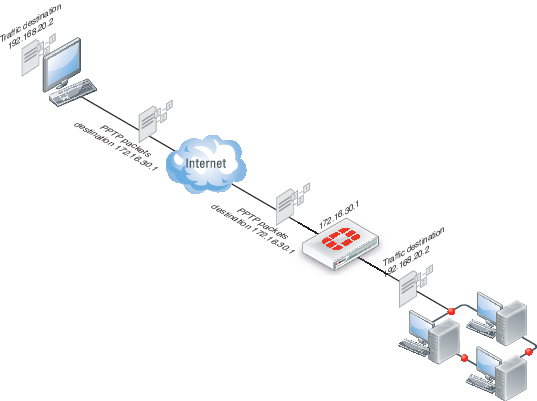
Shown above, traffic from the remote client is addressed to a computer on the network behind the FortiGate unit. When the PPTP tunnel is established, packets from the remote client are encapsulated and addressed to the FortiGate unit. The FortiGate unit forwards disassembled packets to the computer on the internal network.
When the remote PPTP client connects, the FortiGate unit assigns an IP address from a reserved range of IP addresses to the client PPTP interface. The PPTP client uses the assigned IP address as its source address for the duration of the connection.
When the FortiGate unit receives a PPTP packet, the unit disassembles the PPTP packet and forwards the packet to the correct computer on the internal network. The security policy and protection profiles on the FortiGate unit ensure that inbound traffic is screened and processed securely.
|
|
PPTP clients must be authenticated before a tunnel is established. The authentication process relies on FortiGate user group definitions, which can optionally use established authentication mechanisms such as RADIUS or LDAP to authenticate PPTP clients. All PPTP clients are challenged when a connection attempt is made. |
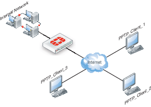
FortiGate unit as a PPTP server
In the most common Internet scenario, the PPTP client connects to an ISP that offers PPP connections with dynamically-assigned IP addresses. The ISP forwards PPTP packets to the Internet, where they are routed to the FortiGate unit.
FortiGate unit as a PPTP server
If the FortiGate unit will act as a PPTP server, there are a number of steps to complete:
- Configure user authentication for PPTP clients.
- Enable PPTP.
- Specify the range of addresses that are assigned to PPTP clients when connecting
- Configure the security policy.
Configuring user authentication for PPTP clients
To enable authentication for PPTP clients, you must create user accounts and a user group to identify the PPTP clients that need access to the network behind the FortiGate unit. Within the user group, you must add a user for each PPTP client.
You can choose to use a plain text password for authentication or forward authentication requests to an external RADIUS, LDAP, or TACACS+ server. If password protection will be provided through a RADIUS, LDAP, or TACACS+ server, you must configure the FortiGate unit to forward authentication requests to the authentication server.
This example creates a basic user/password combination.
Configuring a user account
To add a local user - web-based manager
- Go to User & Device > User > User Definition and select Create New.
- Select Local User
- Enter a User Name.
- Enter a Password for the user. The password should be at least six characters.
- Select OK.
To add a local user - CLI
config user local
edit <username>
set type password
set passwd <password>
end
Configuring a user group
To ease configuration, create user groups that contain users in similar categories or departments.
To create a user group - web-based manager
- Go to User & Device > User > User Group and select Create New.
- Enter a Name for the group.
- Select the Type of Firewall.
- From the Available Users list, select the required users and select the right-facing arrow to add them to the Members list.
- Select OK.
To create a user group - CLI
config user group
edit <group_name>
set group-type firewall
set member <user_names>
end
Enabling PPTP and specifying the PPTP IP address range
The PPTP address range specifies the range of addresses reserved for remote PPTP clients. When a PPTP client connects to the FortiGate unit, the client is assigned an IP address from this range. Afterward, the FortiGate unit uses the assigned address to communicate with the PPTP client.
The address range that you reserve can be associated with private or routable IP addresses. If you specify a private address range that matches a network behind the FortiGate unit, the assigned address will make the PPTP client appear to be part of the internal network.
PPTP requires two IP addresses, one for each end of the tunnel. The PPTP address range is the range of addresses reserved for remote PPTP clients. When the remote PPTP client establishes a connection, the FortiGate unit assigns an IP address from the reserved range of IP addresses to the client PPTP interface or retrieves the assigned IP address from the PPTP user group. If you use the PPTP user group, you must also define the FortiGate end of the tunnel by entering the IP address of the unit in Local IP (web‑based manager) or local‑ip (CLI). The PPTP client uses the assigned IP address as its source address for the duration of the connection.
PPTP configuration is only available through the CLI. In the example below, PPTP is enabled with the use of an IP range of 182.168.1.1 to 192.168.1.10 for addressing and the user group is hr_staff.
|
|
The start and end IPs in the PPTP address range must be in the same 24-bit subnet, for example, 192.168.1.1 - 192.168.1.254. |
config vpn pptp
set status enable
set ip-mode range
set eip 192.168.1.10
set sip 192.168.1.1
set usrgrp hr_staff
end
In this example, PPTP is enabled with the use of a user group for addressing, where the IP address of the PPTP server is 192.168.1.2 and the user group is hr_admin.
config vpn pptp
set status enable
set ip-mode range
set local-ip 192.168.2.1
set usrgrp hr_admin
end
Adding the security policy
The security policy specifies the source and destination addresses that can generate traffic inside the PPTP tunnel and defines the scope of services permitted through the tunnel. If a selection of services are required, define a service group.
To configure the firewall for the PPTP tunnel - web-based manager
- Go to Policy & Objects > Policy > IPv4 or Policy & Objects > Policy > IPv6 and select Create New.
- Complete the following and select OK:
| Incoming Interface | The FortiGate interface connected to the Internet. |
| Source Address | Select the name that corresponds to the range of addresses that you reserved for PPTP clients. |
| Outgoing Interface | The FortiGate interface connected to the internal network. |
| Destination Address | Select the name that corresponds to the IP addresses behind the FortiGate unit. |
| Schedule | always |
| Service | ALL |
| Action | ACCEPT |
To configure the firewall for the PPTP tunnel - CLI
config firewall policy or config firewall policy6
edit 1
set srcintf <interface to internet>
set dstintf <interface to internal network>
set srcaddr <reserved_range>
set dstaddr <internal_addresses>
set action accept
set schedule always
set service ALL
end
Configuring the FortiGate unit for PPTP VPN
To arrange for PPTP packets to pass through the FortiGate unit to an external PPTP server, perform the following tasks in the order given:
- Configure user authentication for PPTP clients.
- Enable PPTP on the FortiGate unit and specify the range of addresses that can be assigned to PPTP clients when they connect.
- Configure PPTP pass through on the FortiGate unit.
Configuring the FortiGate unit for PPTP pass through
To forward PPTP packets to a PPTP server on the network behind the FortiGate unit, you need to perform the following configuration tasks on the FortiGate unit:
- Define a virtual IP address that points to the PPTP server.
- Create a security policy that allows incoming PPTP packets to pass through to the PPTP server.
|
|
The address range is the external (public) ip address range which requires access to the internal PPTP server through the FortiGate virtual port-forwarding firewall. IP addresses used in this document are fictional and follow the technical documentation guidelines specific to Fortinet. Real external IP addresses are not used. |
Configuring a virtual IP address
The virtual IP address will be the address of the PPTP server host.
To define a virtual IP for PPTP pass through - web-based manager
- Go to Policy & Objects > Objects > Virtual IPs.
- Select Create New.
- Choose the VIP Type.
- Enter the name of the VIP, for example,
PPTP_Server. - Select the External Interface where the packets will be received for the PPTP server.
- Enter the External IP Address for the VIP.
- Select Port Forwarding.
- Set the Protocol to TCP.
- Enter the External Service Port of
1723, the default for PPTP. - Enter the Map to Port to
1723. - Select OK.
To define a virtual IP for PPTP pass through - web-based manager
config firewall vip or config firewall vip6
edit PPTP_Server
set extintf <interface>
set extip <ip_address>
set portforward enable
set protocol tcp
set extport 1723
set mappedport 1723
set mappedip <destination IP address range>
end
You can also use config firewall vip46 to define a virtual IP from an IPv4 address to an IPv6 address or config firewall vip64 to define a virtual IP from an IPv6 address to an IPv4 address.
Configuring a port-forwarding security policy
To create a port-forwarding security policy for PPTP pass through you must first create an address range reserved for the PPTP clients.
To create an address range - web-based manager
- Go to Policy & Objects > Objects > Addresses and select Create New.
- Select a Category.
- Enter a Name for the range, for example,
External_PPTP. - Select a Type of Subnet/IP Range.
- Enter the IP address range.
- Select the Interface to the Internet.
- Select OK.
To create an address range - CLI
config firewall address OR config firewall address6
edit External_PPTP
set type iprange
set start-ip <ip_address>
set end-ip <ip_address>
set associated-interface <internet_interface>
end
With the address set, you can add the security policy.
To add the security policy - web-based manager
- Go to Policy & Objects > Policy > IPv4 or Policy & Objects > Policy > IPv6 and select Create New.
- Complete the following and select OK:
| Incoming Interface | The FortiGate interface connected to the Internet. |
| Source Address | Select the address range created in the previous step. |
| Outgoing Interface | The FortiGate interface connected to the PPTP server. |
| Destination Address | Select the VIP address created in the previous steps. |
| Schedule | always |
| Service | PPTP |
| Action | ACCEPT |
To add the security policy - CLI
config firewall policy or config firewall policy6
edit <policy_number>
set srcintf <interface to internet>
set dstintf <interface to PPTP server>
set srcaddr <address_range>
set dstaddr <PPTP_server_address>
set action accept
set schedule always
set service PPTP
end
Testing PPTP VPN connections
To confirm that a PPTP VPN between a local network and a dialup client has been configured correctly, at the dialup client, issue a ping command to test the connection to the local network. The PPTP VPN tunnel initializes when the dialup client attempts to connect.
Logging VPN events
PPTP VPN, activity is logged when enabling VPN logging. The FortiGate unit connection events and tunnel status (up/down) are logged.
To log VPN events
- Go to Log & Report > Log Config > Log Settings.
- Enable the storage of log messages to one or more locations.
- Select VPN activity event.
- Select Apply.
To view event logs
- Go to Log & Report > Event Log > VPN.
- If the option is available from the Log Type list, select the log file from disk or memory.
Configuring L2TP VPNs
This section describes how to configure a FortiGate unit to establish a Layer Two Tunneling Protocol (L2TP) tunnel with a remote dialup client. The FortiGate implementation of L2TP enables a remote dialup client to establish an L2TP tunnel with the FortiGate unit directly.
According to RFC 2661, an Access Concentrator (LAC) can establish an L2TP tunnel with an L2TP Network Server (LNS). In a typical scenario, the LAC is managed by an ISP and located on the ISP premises; the LNS is the gateway to a private network. When a remote dialup client connects to the Internet through the ISP, the ISP uses a local database to establish the identity of the caller and determine whether the caller needs access to an LNS through an L2TP tunnel. If the services registered to the caller indicate that an L2TP connection to the LNS is required, the ISP LAC attempts to establish an L2TP tunnel with the LNS.
A FortiGate unit can be configured to act as an LNS. The FortiGate implementation of L2TP enables a remote dialup client to establish an L2TP tunnel with the FortiGate unit directly, bypassing any LAC managed by an ISP. The ISP must configure its network access server to forward L2TP traffic from the remote client to the FortiGate unit directly whenever the remote client requires an L2TP connection to the FortiGate unit.
When the FortiGate unit acts as an LNS, an L2TP session and tunnel is created as soon as the remote client connects to the FortiGate unit. The FortiGate unit assigns an IP address to the client from a reserved range of IP addresses. The remote client uses the assigned IP address as its source address for the duration of the connection.
More than one L2TP session can be supported on the same tunnel. FortiGate units can be configured to authenticate remote clients using a plain text user name and password, or authentication can be forwarded to an external RADIUS or LDAP server. L2TP clients are authenticated as members of a user group.
|
|
For site-to-site connections, Windows servers use IPsec encryption when you configure the VPN to connect to an L2TP server. |
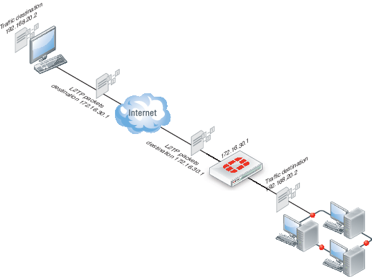
Traffic from the remote client must be encrypted using IPsec before it is encapsulated and routed to the FortiGate unit. Packets originating at the remote client are addressed to a computer on the private network behind the FortiGate unit. Encapsulated packets are addressed to the public interface of the FortiGate unit. See the figure below.
When the FortiGate unit receives an L2TP packet, the unit disassembles the packet and forwards the packet to the correct computer on the internal network. The security policy and protection profiles on the FortiGate unit ensure that inbound traffic is screened and processed securely.
L2TP encapsulation
FortiGate units cannot deliver non-IP traffic such as Frame Relay or ATM frames encapsulated in L2TP packets — FortiGate units support the IPv4 and IPv6 addressing schemes only
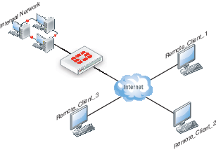
Network topology
The remote client connects to an ISP that determines whether the client requires an L2TP connection to the FortiGate unit. If an L2TP connection is required, the connection request is forwarded to the FortiGate unit directly.
Example L2TP configuration
L2TP infrastructure requirements
- The FortiGate unit must be operating in NAT mode and have a static public IP address.
- The ISP must configure its network access server to forward L2TP traffic from remote clients to the FortiGate unit directly.
- The remote client must not generate non-IP traffic (Frame Relay or ATM frames).
L2TP configuration overview
To configure a FortiGate unit to act as an LNS, you perform the following tasks:
- Create an L2TP user group containing one user for each remote client.
- Enable L2TP on the FortiGate unit and specify the range of addresses that can be assigned to remote clients when they connect.
- Define firewall source and destination addresses to indicate where packets transported through the L2TP tunnel will originate and be delivered.
- Create the security policy and define the scope of permitted services between the source and destination addresses.
- Configure the remote clients.
Authenticating L2TP clients
L2TP clients must be authenticated before a tunnel is established. The authentication process relies on FortiGate user group definitions, which can optionally use established authentication mechanisms such as RADIUS or LDAP to authenticate L2TP clients. All L2TP clients are challenged when a connection attempt is made.
To enable authentication, you must create user accounts and a user group to identify the L2TP clients that need access to the network behind the FortiGate unit.
You can choose to use a plain text password for authentication or forward authentication requests to an external RADIUS or LDAP server. If password protection will be provided through a RADIUS or LDAP server, you must configure the FortiGate unit to forward authentication requests to the authentication server.
Enabling L2TP and specifying an address range
The L2TP address range specifies the range of addresses reserved for remote clients. When a remote client connects to the FortiGate unit, the client is assigned an IP address from this range. Afterward, the FortiGate unit uses the assigned address to communicate with the remote client.
The address range that you reserve can be associated with private or routable IP addresses. If you specify a private address range that matches a network behind the FortiGate unit, the assigned address will make the remote client appear to be part of the internal network.
To enable L2TP and specify the L2TP address range, use the config vpn l2tp CLI command.
The following example shows how to enable L2TP and set the L2TP address range using a starting address of 192.168.10.80 and an ending address of 192.168.10.100 for an existing group of L2TP users named L2TP_users:
config vpn l2tp
set sip 192.168.10.80
set eip 192.168.10.100
set status enable
set usrgrp L2TP_users
end
Defining firewall source and destination addresses
Before you define the security policy, you must define the source and destination addresses of packets that are to be transported through the L2TP tunnel:
- For the source address, enter the range of addresses that you reserved for remote L2TP clients (for example
192.168.10.[80-100]). - For the destination address, enter the IP addresses of the computers that the L2TP clients need to access on the private network behind the FortiGate unit (for example,
172.16.5.0/24for a subnet, or172.16.5.1for a server or host, or192.168.10.[10-15]for an IP address range).
To define the firewall source address
- Go to Policy & Objects > Objects > Addresses and select Create New.
- Select a Category.
- In the Address Name field, type a name that represents the range of addresses that you reserved for remote clients (for example,
Ext_L2TPrange). - In Type, select IP Range.
- In the IP Range field, type the corresponding IP address range.
- In Interface, select the FortiGate interface that connects to the clients.
- This is usually the interface that connects to the Internet.
- Select OK.
To define the firewall destination address
- Go to Policy & Objects > Objects > Addresses and select Create New.
- In the Address Name field, type a name that represents a range of IP addresses on the network behind the FortiGate unit (for example,
Int_L2TPaccess). - In Type, select IP Range.
- In the IP Range field, type the corresponding IP address range.
- In Interface, select the FortiGate interface that connects to the network behind the FortiGate unit.
- Select OK.
Adding the security policy
The security policy specifies the source and destination addresses that can generate traffic inside the L2TP tunnel and defines the scope of services permitted through the tunnel. If a selection of services are required, define a service group.
To define the traffic and services permitted inside the L2TP tunnel
- Go to Policy & Objects > Policy > IPv4 or Policy & Objects > Policy > IPv6 and select Create New.
- Enter these settings:
| Incoming Interface | Select the FortiGate interface to the Internet. |
| Source Address | Select the name that corresponds to the address range that reserved for L2TP clients (for example, Ext_L2TPrange). |
| Outgoing Interface | Select the FortiGate interface to the internal (private) network. |
| Destination Address | Select the name that corresponds to the IP addresses behind the FortiGate unit (for example, Int_L2TPaccess). |
| Service | Select ALL, or if selected services are required instead, select the service group that you defined previously. |
| Action | ACCEPT |
- Select OK.
Configuring a Linux client
This procedure outlines how to install L2TP client software and run an L2TP tunnel on a Linux computer. Obtain an L2TP client package that meets your requirements (for example, rp-l2tp). If needed to encrypt traffic, obtain L2TP client software that supports encryption using IPsec.
To establish an L2TP tunnel with a FortiGate unit that has been set up to accept L2TP connections, you can obtain and install the client software following these guidelines:
- If encryption is required, you will need to verify the IPsec configuration.
- Download and install the L2TP client package.
- Configure an L2TP connection to run the L2TP program.
- Configure routes to determine whether all or some of your network traffic will be sent through the tunnel. You must define a route to the remote network over the L2TP link and a host route to the FortiGate unit.
- Run
l2tpdto start the tunnel.
Follow the software supplier’s documentation to complete the steps.
To configure the system, you need to know the public IP address of the FortiGate unit, and the user name and password that has been set up on the FortiGate unit to authenticate L2TP clients. Contact the FortiGate administrator if required to obtain this information.
Monitoring L2TP sessions
You can display a list of all active sessions and view activity by port number. By default, port 1701 is used for L2TP VPN-related communications. If required, active sessions can be stopped from this view. Use the Top Sessions Dashboard Widget.
Testing L2TP VPN connections
To confirm that a VPN between a local network and a dialup client has been configured correctly, at the dialup client, issue a ping command to test the connection to the local network. The VPN tunnel initializes when the dialup client attempts to connect.
Logging L2TP VPN events
You can configure the FortiGate unit to log VPN events. For L2TP VPNs, connection events and tunnel status (up/down) are logged.
To log VPN events - web-based manager
- Go to Log & Report > Log Config > Log Settings.
- Enable the storage of log messages to one or more locations.
- Select Enable, and then select VPN activity event.
- Select Apply.
To log VPN events - CLI
config log memory setting
set diskfull overwrite
set status enable
end
config log eventfilter
set vpn enable
end
Copyright © 2018 Fortinet, Inc. All Rights Reserved. | Terms of Service | Privacy Policy
